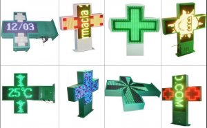
LED Video screens
Action # 2: Connect Teensy and Octo guard
Solder the headers on your Teensy then connect your OctoWS2811 Adaptor. The Teensy will receive video from your own PC and then transform it to the language of LEDs.
Action no. 3: Solder power connectors to LEDS
Solder a male T-connector every single Light-emitting Diode strip, and a female T-connector to only 18 of this pieces. Arrows on strip point to the feminine end; energy goes in during the male end and out in the female. The pieces will alternate course in a zigzag structure so power can go through 2 at any given time (and data 12 at any given time). Therefore be constant regarding your cable colors! Changing at the center would break the Ghostbusters Rule (don’t mix the channels).
Step no. 4: Prepare the information cable
- Remove 12" from one end of this CAT5 cable to expose the 4 line sets in.
- The feminine JST SM connector has 3 wires: white, green, and purple. The purple one’s perhaps not utilized here. Solder the green someone to the lime CAT5 cable, and solder the white anyone to the orange/white CAT5 wire. Now you have actually a CAT5 cable who has RJ45 on a single end and a SM connector on the other side.
- Solder female SM connectors to 2 much more revealed pairs: blue and blue/white, and green and green/white. The brown and brown/white set just isn't used. Double-check work — and label both stops to help you type all of them later on.
Step no. 5: Prepare the energy cables
- One CAT5 cable can run 8 Light-emitting Diode pieces, so you’ll need each of 4 cables and some of a fifth cable. They’re all ready exactly the same. Take one 9'-long CAT5 cable and expose the line pairs at both ends. One solid colored CAT5 cable will hook up to one purple energy line on an LED strip. The white CAT5 cable will hook up to the white power cable in the Light-emitting Diode strip.
- We soldered feminine T-connectors right here also, so we could unplug the cables.
Action # 6: Sew the velcro (optional)
We sewed a velcro edge in the straight back associated with textile, therefore we can potentially dismantle and roll up the Light-emitting Diode wall surface. You need to use the velcro to install it to a wall or a stand-alone framework.
Action no. 7: Mount the LED strips
Set the fabric flat on the floor. Lay the initial strip during the “top” regarding the wall with all the male end regarding the left (arrows pointing to the right), and place it down using its adhesive backing (extra glue won’t hurt). Lay strip 2 underneath the very first one, with arrows pointing remaining. Perform for several 36 LED pieces. We utilized hiding tape with calculated scars to make sure our strips had been uniformly spaced.
Action #8: Link power
- Stick to the power wiring drawing for connecting capacity to every 2nd strip. Regarding the remaining part, connect every strange strip (1, 3, 5, etc.) to an electrical cable. From the right-side, link strip one to two, then 3 to 4, etc., right down.
- Each power cable after that connects to an electric offer — solid colors to VCC, white wires to GND.
Action no. 9: Connect information
- You’ll connect the information cables in 12-strip blocks. Connect Data line 1 (orange and orange/white) towards first Light-emitting Diode strip’s male SM connector. After that connect the second 11 pieces, zigzagging, down through strip 12. Connect Data line 2 (blue and blue/ white) to remove 13’s male SM connector, zigzagging down through strip 24. Connect information line 3 (green and green/white) to strip 25’s male SM connector, zigzagging through strip 36.
- Today plug the information cable’s CAT5 connector in to the Octo shield’s interface 1.
Step #10: cable the energy supplies
- Slice the end off the three Computer power cables, strip the cables, and link all of them into energy supplies. Keep in mind that black colored visits (L) reside, white to (letter) Neutral, and green to Earth (ground).
- We found it easiest to use a power splitter in order for one switch could control the entire wall surface.
Action #11: Program the Teensy
Download the Arduino sketch the Teensy from Github, then upload it into board utilizing the Arduino IDE. Whenever Teensy reboots and you also turn on the Light-emitting Diode wall energy, it should show a test pattern. Or even, check your energy connections plus the Octo shield connection.
Action #12: test thoroughly your jumbotron!
Grab the Processing sketch from Github too, and operate it on your desktop. A section of your display should appear on the LED wall. Move your movie system into that part of your display and struck Enjoy. Turn your speakers way-up. Make popcorn, switch off the lights, and enjoy.
RELATED VIDEO


Share this Post
Related posts
Video Screens
Since 2012, things have actually altered a lot when it comes to recording your iPhone or iPad screens. The essential known…
Read MoreLED video display panels
Using our 16x32 RGB LED matrix panels and some patience, you ll develop a crazy brilliant professional Light-emitting Diode…
Read More


